
As part of the carbon capture storage (CCS) process, geologic sequestration (GS) refers to a suite of technologies that are deployed to reduce CO2 emissions to the atmosphere and help mitigate climate change. GS involves injecting CO2 into deep subsurface rock formations for long-term storage.
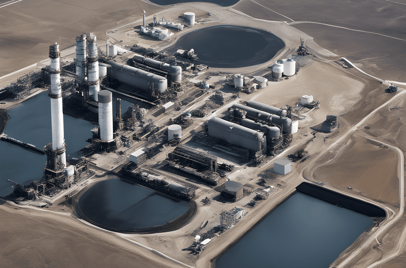
CO2 is first captured from fossil fueled power plants or other emission sources such as natural gas processing facilities, petroleum refineries, iron and steel foundries, ethylene plants, hydrogen production facilities, ammonia refineries, ethanol production facilities, ethylene oxide plants and cement kilns. Operators typically compress CO2 to convert it from a gaseous state to a supercritical fluid state where it exists at high pressures, exhibiting properties of both a liquid and a gas. The CO2 is then transported to GS sites, where in a supercritical state, it is injected into rock formations to depths greater than 800 meters (2,645 feet) for the purpose of maximizing capacity and storage.
When injected into an appropriate receiving formation, CO2 is sequestered by a combination of trapping mechanisms, including physical and geochemical processes. Physical trapping occurs when the relatively buoyant CO2 rises in the formation until it reaches a stratigraphic zone with low permeability that inhibits further upward migration. Physical trapping can also occur as residual CO2 is immobilized in formation pore spaces as disconnected droplets or bubbles at the trailing edge of the plume due to capillary forces. A portion of the CO2 will dissolve from the pure fluid phase into native groundwater and hydrocarbons. Geochemical trapping occurs when chemical reactions between the dissolved CO2 and minerals in the formation lead to the precipitation of solid carbonate minerals. The timeframe over which CO2 will be trapped by these mechanisms depends on properties of the receiving formation and the injected CO2 stream.
According to the United States Environmental Protection Agency (EPA), as of March 2023 a total of two commercial-scale Class VI wells are in operation in the U.S., with 73 projects awaiting permits. Due to the large CO2 injection volumes occurring and/or planned at these well sites, the relative buoyancy of CO2, its mobility within subsurface geologic formations, its corrosivity in the presence of water, and the potential presence of impurities in the captured CO2 stream, the EPA has determined that existing Underground Injection Control (UIC) regulations for Class VI wells are necessary to manage the unique nature of CO2 injection for GS. A critical component of these regulations encompasses monitoring, reporting and verification (MRV).
Monitoring, Reporting and Verification
Monitoring, reporting and verification associated with GS injection projects is an important component of the UIC program. MRV data can be used to verify that the injectate is safely confined in the target formation, minimize costs, maintain the efficiency of the storage operation, and confirm that injection zone pressure changes follow predictions.
The EPA’s established MRV requirements for GS projects, including sub-seabed offshore formations, are built upon long standing programmatic requirements for underground injection in place since the 1980s, with periodic updates including the February 22, 2023 release, Geologic Sequestration of Carbon Dioxide, 40 CFR Part 98 Subpart RR. These requirements are designed to prevent CO2 movement into Underground Source of Drinking Waters (USDWs) by addressing the potential pathways through which injected CO2 fluids can migrate into USDWs and cause endangerment to human water usage supplies.
These mandates address the following: a) Site characterization with an assessment of the geologic, hydrogeologic, geochemical and geomechanical properties of the proposed GS site to ensure that wells are located in suitable formations; b) Well construction using materials that can withstand contact with CO2 over the life of the GS project; c) Computational modeling that accounts for the physical and chemical properties of the injected CO2 based on available site characterization, monitoring and operational data; and d) Periodic re-evaluation to incorporate monitoring and operational data and verify that the CO2 plume and the associated area of elevated pressure are moving as predicted within the subsurface.
GS sites are required to develop and implement a site-specific MRV plan which, once approved by the EPA, would be used to verify the amount of CO2 sequestered and to quantify emissions if injected CO2 leaks to the surface. The GS reports must include information to outline how monitoring will achieve surface detection and quantification of CO2, and the amount (flow rate) of injected CO2 for the mass balance equation that will be used to quantify the amount of CO2 sequestered by a facility.
Robust oversight must be maintained of the CO2 stream, injection pressures, integrity of the injection well, groundwater quality and geochemistry, and monitoring of the CO2 plume and position of the pressure front throughout injection. Additionally, comprehensive post-injection monitoring following cessation of injection is required to show the position of the CO2 plume and the associated area of elevated pressure to demonstrate that neither poses an endangerment to USDWs.
Mechanical Integrity Testing (MIT)
Injection well MIT is a critical component of the EPA’s UIC program’s requirements designed to ensure USDW protection from endangerment. Testing and monitoring the integrity of an injection well at an appropriate frequency throughout the injection operation, in conjunction with corrosion monitoring of well materials, can verify that the injection system is operating as intended or provide notice that there may be a loss of containment that may lead to endangerment of USDWs.
Routine MITs enable operators to ensure that well integrity is maintained from construction throughout the life of the injection project. UIC regulations require injection well operators to demonstrate both internal and external mechanical integrity.
Internal mechanical integrity is an absence of significant leakage in the injection tubing, casing, or packer. Leakage occurs due to corrosion or mechanical failure of the injection well’s tubular and mechanical components. UIC regulations require continuous monitoring to demonstrate well integrity. This is driven by concerns that the potential corrosivity of CO2 in the presence of water and the anticipated high pressures and volumes of injectate could compromise the integrity of the well. Continuous monitoring is essential because it allows for the immediate identification of corrosion-related mechanical integrity problems or problems due to temperature and pressure effects associated with injection of supercritical CO2.
External well mechanical integrity is demonstrated by establishing the absence of significant fluid movement along the outside of the casing, generally between the cement and the well structure, and between the cement and the well-bore. Failure of an external MIT can indicate improper cementing or degradation of the cement that was replaced to fill and seal the annular space between the outside of the casing and the well-bore. This type of failure can lead to movement of injected fluids out of intended injection zones and toward USDWs. The EPA requires operators of CO2 injection wells to demonstrate external mechanical integrity at least once annually during injection operations using a tracer survey or a temperature or noise log.
Groundwater/Geochemical
Groundwater and geochemical monitoring are important to ensure protection of USDWs from endangerment, preserve water quality, and allow for detection of any leakage of CO2 or displaced formation fluids out of the target formation and/or through the confining layer.
Periodically analyzing groundwater quality – salinity, pH, and aqueous and pure-phase CO2 – above the confining layer can reveal geochemical changes that result from leaching or mobilization of heavy metals and organic compounds, or fluid displacement. The EPA requires periodic monitoring of the groundwater quality and geochemical changes above the confining zone, based on a flexible monitoring regime, with the amounts and types of monitoring being site specific.
Pressure Fall-Off Testing
Pressure fall-off tests are designed to determine if reservoir pressures are tracking as predicted. The results of pressure fall-off tests will confirm site characterization information and verify that projects are operating properly, and that the injection zone is responding as predicted.
Pressure fall-off testing provides valuable information, and the EPA specifies that a five-year frequency is appropriate. The EPA believes that this frequency will allow for adequate pressure tracking in the injection formation. It will also help to verify that the operation is responding as modeled and predicted and allow the operator to take appropriate action if the monitoring results do not match expectations.
Monitoring CO2 Plume and Pressure Front
Monitoring the movement of the CO2 and the pressure front are necessary to identify potential risks to USDWs posed by injection activities, verify predictions of plume movement, provide inputs for modeling, identify needed corrective actions, and target other monitoring activities.
UIC regulations require tracking of the plume and pressure front by direct pressure monitoring via monitoring wells in the first formation overlying the confining zone, or by using indirect geophysical techniques such as seismic profiling, electrical, gravity, electromagnetic surveys, or down-hole CO2 detection tools.
The EPA adds that operators may consider performing additional pressure monitoring in wells that are above the confining zone to provide additional verification that no pressure changes are occurring above the confining zone due to CO2 leakage or displacement of native fluids.
Additional MRV Requirements
The EPA recognizes that monitoring and testing technologies used at GS sites will vary and be project-specific, influenced by both geologic conditions and project characteristics. At certain sites additional monitoring may be needed.
UIC regulations require GS site operators to submit the results of required periodic testing and monitoring associated with the GS project to the EPA.
Distributed Fiber Optic Sensing in Support of Geologic Sequestration MRV
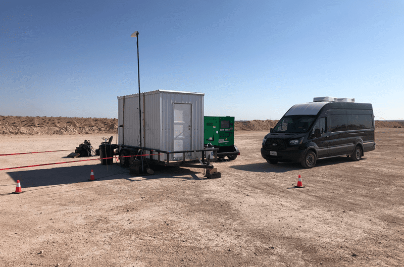
The deployment of fully distributed fiber optic sensors into deep wells to monitor acoustic vibrations, mechanical strain, reservoir temperature and reservoir pressure distribution, in support of oil and gas down hole applications and CO2 injection, has advanced considerably over the last decade.
Because a fiber optic cable can be installed in harsh environments for long periods of time, the technology holds promise for environmental monitoring of sensitive subsurface operations. Many geofluid systems, including GS, require dynamic acoustic, temperature, strain and pressure monitoring at great pressure, depth and temperature. Sensing systems that employ downhole fiber optic cables serve particularly well for long-term well monitoring and well-integrity monitoring.
Distributed fiber optic sensing provides the critical capability of measuring multiple physical phenomena along the entire length of an internal borehole, as well as monitoring the conditions of the near-wellbore region, outside of pipe subsurface rock formations, supporting verification and accounting of geologic carbon sequestration projects.
Distributed fiber optic sensing technologies that support GS include Distributed Acoustic Sensing (DAS), Distributed Temperature Sensing (DTS), Distributed Pressure Sensing (DPS), and Distributed Temperature Strain Sensing (DTSS). While DAS and DTS technologies have achieved success in many GS applications, DTSS provides not only temperature, but also the absolute, differential time lapse and dynamic strain deformation profiles along the full length of optical fiber, over distances reaching up to tens of kilometers. Distributed Pressure Sensing is in development and shows great promise in lab development and testing. It has yet to be proven at field level.
As good as DAS, DTS and DTSS technologies are, the increasing demand for monitoring geofluid systems, like geologic sequestration, has encouraged further development of specialized technologies capable of very high sensitivity and reliability, along with mechanical robustness suitable for harsh operational environments. One of these more recently developed technologies, Distributed Strain Sensing Rayleigh Frequency Shift (DSS-RFS), represents a significant breakthrough for geologic sequestration MRV. It leverages significant advancements in hydrocarbon production operations and has clear crossover applications to GS applications.
Distributed Strain Sensing Rayleigh Frequency Shift (DSS-RFS)
The latest generation of fiber optic sensing systems employed to monitor deep well conditions, Distributed Strain Sensing Rayleigh Frequency Shift (DSS-RFS) is a truly transformative technology for augmenting operational performance in GS. Providing critical data about the downhole well environment from distributed fiber optic sensing, DSS-RFS improves the ability of engineers and scientists to more efficiently and effectively understand strain and temperature dynamics of the subsurface and support engineering operational, monitoring, reporting and verification activities and goals that support GS.
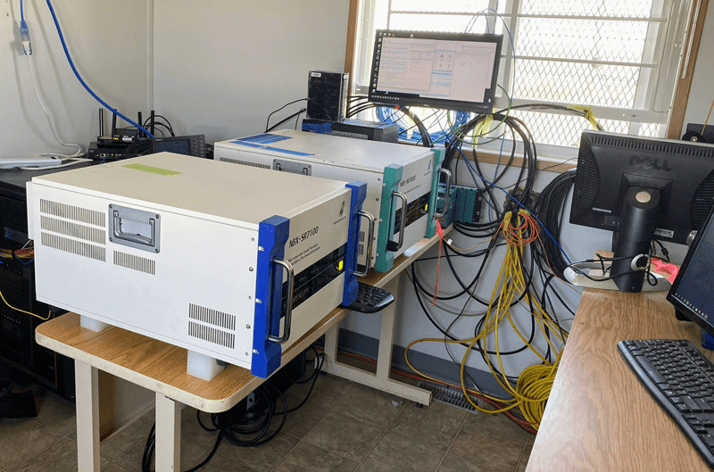
DSS-RFS uses Rayleigh Wavelength, optically sourced backscatter in a nonengineered single mode silica (glass) fiber to measure strain and temperature changes along the fiber. Advanced through research, development and field application by Neubrex Ltd., Kobe, Japan, distributed fiber optic-based strain and temperature sensing measurements are made based on the frequency shift of the Rayleigh optical scattering spectrum, which is linearly dependent on strain and temperature changes applied to the sensing fiber. Strain changes along the wellbore are continuously measured at fine spatial scale during operations of the GS well.
The principle of the DSS-RFS method can be explained accordingly: When an optical fiber is manufactured, random inhomogeneities of the glass density are created in the fiber core. The random density heterogeneities manifest as a variation of refractive index along the fiber. For a certain laser frequency, the constructive and destructive interferences between the Rayleigh backscatters cause irregular but unique amplitude fluctuations in the coherent optical time-domain reflectometer along the fiber length. For each discrete fiber segment, a unique Rayleigh scattering spectrum (like a fingerprint) is obtained by scanning the fiber with a coherent optical time-domain reflectometer with a range of laser frequencies using a tunable-wavelength laser system. This unique Rayleigh scattering spectrum shifts in frequency space if the temperature and/or mechanical strain on the fiber section changes, which causes the spacing and optical delay to vary between the scatterers. This change is detectable and measurable with Neubrex technology.
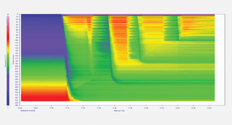
DSS-RFS technology permits tens-of-thousands of points down a fiber that is attached to a tubing string or casing string to be measured very quickly every 20 centimeters along the entire fiber length deployed in or along the wellbore. The continuous glass fiber strand inside the cable can sense very small physical length changes at a large range of frequencies. These measurements of thermally or mechanically-driven strain change, as a function of time and depth, are valuable to engineers who use the data to gain an understanding of what is occurring deep down in the well. No other technology provides such insight.
Changes in temperature (degrees), strain (microstrain unit), acoustics (dB, noise) and pressure (psi) can be made in real-time while CO2 injection is occurring. This helps field engineers understand what is happening in these deep wells much better than with previous discrete sensor-position technologies. Data driven changes or adjustments to operational plans or maintenance plans can then be made when warranted, to optimize the GS operation and make wells with better long-term sequestration performance, efficiency and efficacy.
DSS-RFS is employed in application by Neubrex Energy Services, the U.S. division of Neubrex Ltd. The company’s DTSS product line is known as Neubrescope®. It is actively deployed in North America in different operational settings, such as oil and gas, CCS and geothermal operations.
“Neubrescope DSS-RFS is well designed for monitoring geologic sequestration operations,” says Dana Jurick, executive vice president and general manager of Neubrex Energy Services. “Nevertheless, companies involved in GS are still in the learning, testing, qualification and acceptance phase of using fiber optics and how they can be reliably, safely and economically installed, and used in a well and long term well operations.”
“Once installed in a well, operators are learning what measurements can be made, and how it differs from competing technologies,” adds Jurick. “The value proposition of this technology application is actively being explored by many GS companies, both domestically in the U.S. and internationally in numerous CCS projects.”
New Paradigm for Carbon Sequestration Sites
Monitoring, reporting and verification associated with GS injection projects is an important component of the EPA’s UIC regulations. Fiber optic derived data, combined with other data types, can support MRV requirements and can be used to verify that the CO2 injectate is safely confined in the target formation, minimize costs, maintain the efficiency of the storage operation, and confirm that injection zone pressure changes follow predictions.
MRV requirements can now be better realized with the application of Distributed Strain Sensing Rayleigh Frequency Shift (DSS-RFS), which has set a new paradigm for more efficient monitoring, reporting and verification in geologic carbon sequestration sites.
For more information, contact Dana M. Jurick, Executive Vice President and General Manager, Neubrex Energy Services (US), LLC; 11125 HWY 159 W, Bellville, Texas 77418.
Phone 713-899-1545; email dana.jurick@neubrex.com; www.neubrex.com.

Jim McMahon writes on industrial, manufacturing and technology issues. His features have appeared in more than 3,000 business and trade publications worldwide.

Oil and gas operations are commonly found in remote locations far from company headquarters. Now, it's possible to monitor pump operations, collate and analyze seismic data, and track employees around the world from almost anywhere. Whether employees are in the office or in the field, the internet and related applications enable a greater multidirectional flow of information – and control – than ever before.