
Can the life of mature oil and gas fields be extended through the application of carbon capture, utilization and sequestration (CCUS), profitably? The answer is YES, based on the characteristics of the field and application of carbon credits from the Inflation Reduction Act (IRA).
Background
A typical oil and gas field may produce 20 to 40 percent of its resources under primary and secondary recovery methods. The use of extended reach wells, artificial lift and wellbore stimulation methods, such as hydraulic fracturing, may result in an additional 10 to 20 percent recovery in select fields, but at much higher costs. With the introduction of the IRA in 2018 and significant increase in carbon capture incentives in 2022, the oil and gas industry can extend the productive life of its operations by using sunk costs in existing fields. Majors, such as ExxonMobil and Occidental (Oxy), already have jump-started their transition using carbon capture and storage and CO2 enhanced oil recovery (EOR).
Inflation Reduction Act (IRA) Incentives for CCUS
Let us begin with a brief review of the IRA as it relates to carbon capture. Under Section 45Q of the IRA, various tax incentives are available for reduction of carbon oxides emitted from existing industrial operations including oil and gas fields. Beginning in 2022, these incentives have been increased to $85 per ton of removed carbon oxides. Additionally, enhanced tax credits are offered for direct capture and removal of CO2 from air (DAC). These incentives are at $180 per ton.
Instructions for IRS form 8933 provide the details for qualifications and claims. The form requires information for claiming tax credits related to carbon oxides sequestration. Taxpayer details, facility information, and the amount of qualified carbon oxides captured and stored during the tax year are required. Essential documentation includes certifications, approvals and verification procedures confirming compliance with environmental standards. The form calculates the tax credit based on the captured carbon oxides for the reporting period. Key documentation includes numerical simulations of CO2 flow, pressure monitoring of injection wells, adjacent and confining geological formations, and monitoring of ground water for CO2 breakthrough.
CCS and CCUS
Carbon reductions are in two forms, carbon capture and storage (CCS) and carbon capture utilization and storage (CCUS). In the case of CCS, carbon emissions are captured and injected into secure geological formations for permanent storage using injection wells. Secure geological storage includes, but is not limited to, storage at deep saline formations, oil and gas reservoirs, and unmineable coal seams.
In the case of CCUS, carbon emissions in the form of CO2 are either utilized for EOR or converted by chemical reactions into industrially useful products such as cement. According to the Intergovernmental Panel on Climate Change (IPCC, 2018), up to 20 gigatons of CO2 per year should be captured by 2050. Some 20 percent reduction in CO2 emissions can be achieved with CCS.
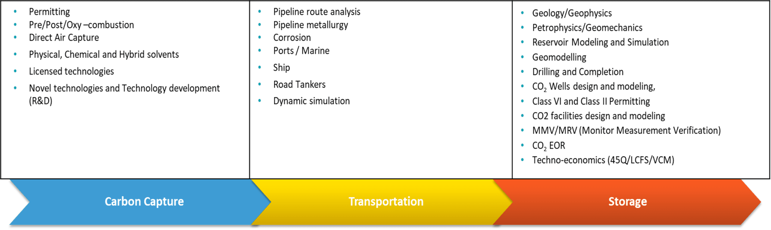
Selection of CCS or CCUS depends on several factors including emission volumes, transportation costs to nearby fields suitable for EOR, suitability of geologic formations for injection and permanent storage, economics of chemical conversions, and expected duration of tax credits for CCS/CCUS. A list of various processes and requirements along the CCUS value chain are outlined in Figure 1.
The fundamentals of carbon capture have not changed in the past 100 years. The focus, however, has been on developing new technologies to lower the cost. Collecting CO2 from a point source, like a smokestack, is the most efficient form of carbon capture as well as the oldest. Point-source carbon capture costs about $70 per metric ton of carbon, about a fifth of the price of capturing the gas once it’s dispersed in the atmosphere. Sequestering CO2 once released, known as direct air capture (DAC), uses carbon scrubbers for extraction. Other methods for capturing carbon are under development.
Transporting CO2 is a proven technology that uses different means of transportation as shown above. It is best to keep CO2 at a supercritical state to maximize the volume that can be transported. Storing it in underground storage spaces is a promising method of sequestering large volumes of CO2. If done correctly, underground storage can be an effective way to sequester CO2 indefinitely. Equinor in Norway, for example, has sequestered about a million tons of CO2 per year since 1996 in the Sleipner undersea gas fields.
As shown in Figure 1, many studies need to be carried out to develop such projects, i.e., geological and reservoir characterization, special well permitting, installation of monitoring devices over the life of the project, facility design and techno-economic feasibility studies.
For example, dynamic simulation helps assess specific technical risks and sensitivities such as:
- Plume containment under different injection schemes
- Assess pressure and stress fields with injection (fault reactivation)
- Interaction of CO2 with brine and residual gas (injectivity, mobility)
- Predict CO2 arrival time to existing wells.
(See “Integrated Aquifer Characterization and Modeling for Energy Sustainability” for details.)
Reservoir Characteristics for CO2 Storage
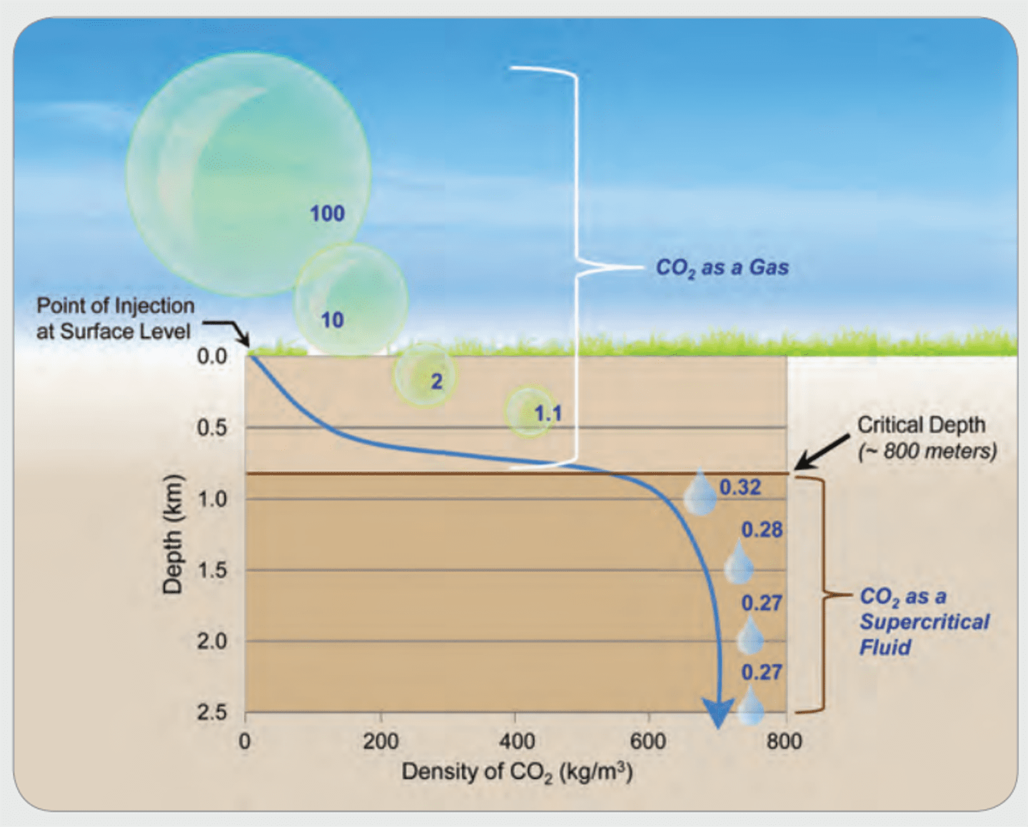
One of the key parameters to consider for storage suitability is the reservoir depth. Figure 2 shows the decrease in CO2 volume with depth. Due to the increase in hydrostatic pressure and temperature, at 800 m (2400 ft), the CO2 volume compresses to about 3.2 percent of its volume at surface conditions. Beyond this depth, the volume shrinkage is not significant (i.e., 2.7 percent at 2500 m depth). Thus, it is important that the candidate reservoir is at least 800 m deep.
Another consideration is the suitability of the reservoir for CO2 EOR. There are several screening criteria to assess the potential application of this EOR method to mature fields. If the conditions for the latter application are met, the additional oil recovery could potentially pay for some of the required CAPEX for injection facilities. Under this scenario, a reliable estimate of the CO2 retention in the reservoir should be obtained. The latter is required for assessing the potential carbon credits due to CO2 storage.
If the economics for CO2 EOR are not positive (i.e., the reservoir has been depleted significantly) or the reservoir is not suitable for this process, then studies for its suitability for CO2 storage need to be undertaken. It is important to include attached aquifer characterization (if any), since its volume could significantly increase the storage capacity for CO2.
CO2 injection rate and the duration of injection are other important considerations. Caution should be exercised not to exceed the original reservoir pressure during injection (unless geomechanical studies indicate top seal integrity at higher reservoir pressure).
An example of simulated reservoir pressure for an offshore field is shown in Figure 3 under three injection scenarios of one, five and 10 million tons per annum (MTPA). Generally, the one MTPA case deals with sequestering the field emissions only. Larger volumes that include bringing in CO2 from other sources may require additional injectors.
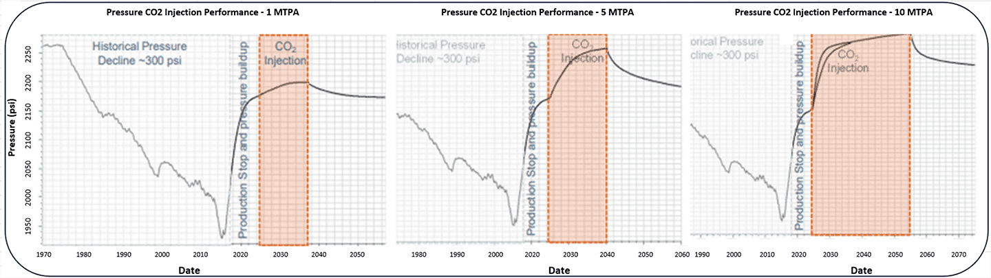
Notice that during depletion, the reservoir pressure declined by 300 psi. During this time, there was a continuous aquifer influx into the reservoir. Following the stoppage of production, and during the injection phase, the reservoir pressure started building up. Only under the one MTPA instance, is the reservoir pressure during injection safely below the initial level. For other scenarios, the operator might consider producing water from the aquifer to reduce the size of pressure buildup. In all three cases, the CO2 plume was contained within the structure during 30 years of simulation.
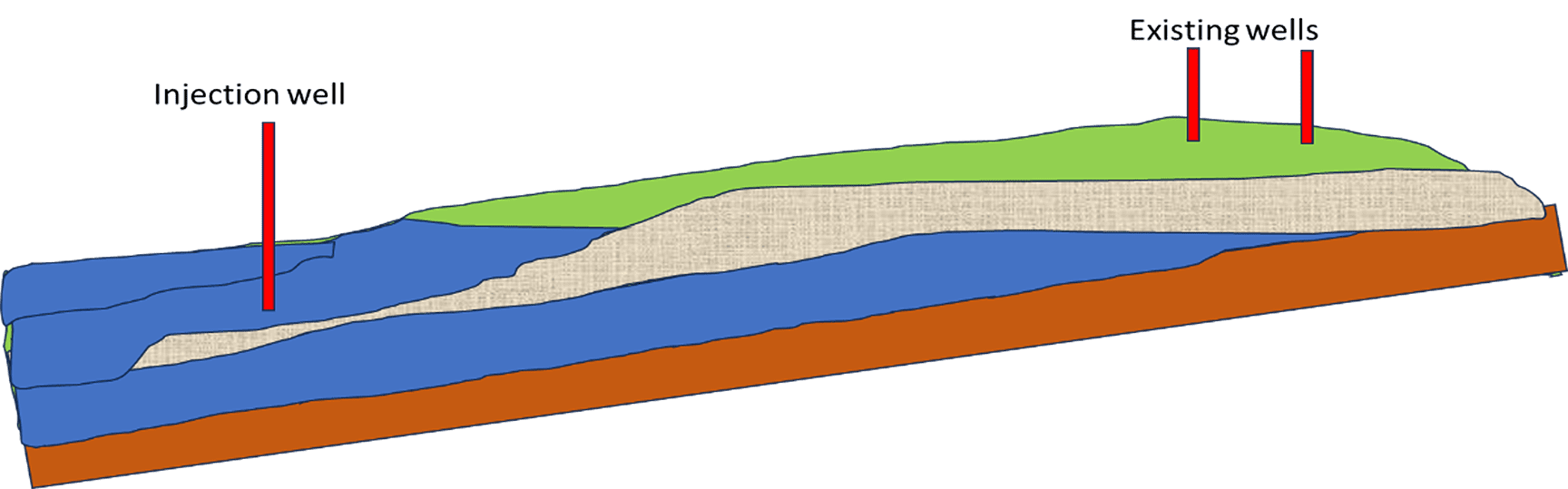
One could either use an existing well for injection or drill a new one. These injection wells are required to comply with the class VI IRA requirements to prevent any leakage behind casing. The key consideration is the migration path. If the well is close to the crest, opportunities for residual and solubility trapping are limited. Ideally, the well should be located at a midpoint between the spill point and crest to allow CO2 plume to migrate towards the crest under buoyancy. Injecting into an existing aquifer could help with timely CO2 plume migration and containment within the structure. An example of an ideal location within a dipping structure is shown in Figure 4.
Consideration of CCS/CCUS for Mature Oil and Gas Fields
In a typical oil and gas field, carbon emissions are associated with power generation, gas lift operations, occasional flaring, field activities or EOR. There is, of course, hydrocarbon based emissions including methane, but these would be treated separately since they do not fall under CCS/CCUS. A simple decision tree, shown below, lays out the evaluation process for extending the economic life of a field supported by carbon credits.
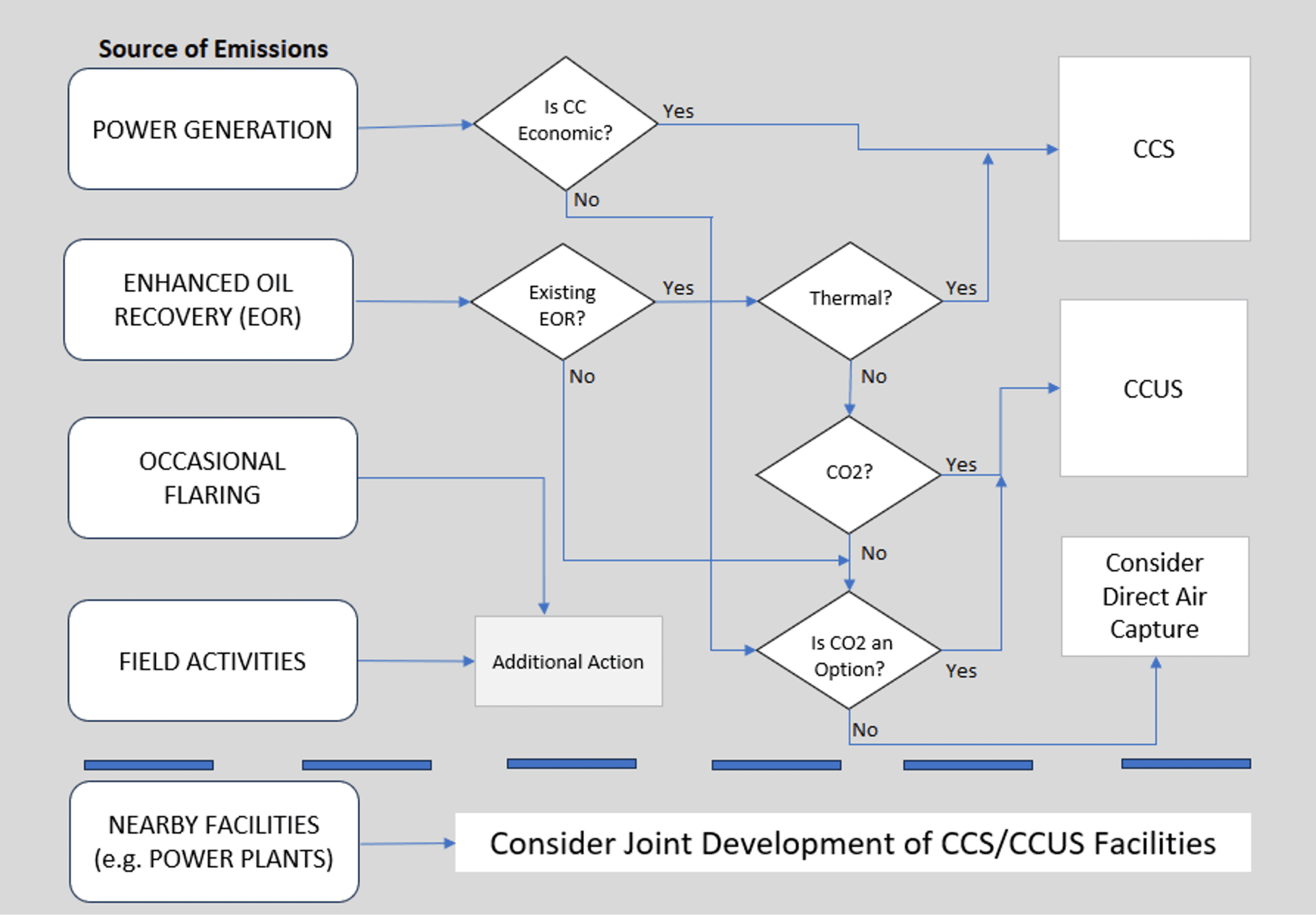
The first step in evaluation is to analyze the total carbon footprint of the field operations, followed by determination of the volume of steady emissions from power generation, compressors, gas lift operations, etc. If emission volumes are large enough to support a stand-alone CCS project, the operator can initiate a feasibility study looking at surface and subsurface options to develop and optimize a forward plan. The study should consider the use of existing facilities, production history, formation data and wells. The owner’s contributions to the overall project cost may include sunk costs for existing infrastructure, wells, and subsurface data, which could support external financing for the project.
In the absence of ongoing EOR operations, direct air capture (DAC) may be deployed as a supplement for carbon emissions from power generation and compensate for cumulative emissions from flaring and field works. DAC volumes will depend on the level of carbon credits and corresponding economics.
For fields with ongoing EOR activities, depending on the type of EOR (i.e., thermal or CO2), screening economics and technical factors (e.g., oil gravity, formation characteristics) point to CCS for thermal, and CCUS for CO2 EOR. Even if the field is not under an ongoing EOR, the addition of DAC can generate sufficient carbon credits with attractive economics.
Finally, a field operator might opt for bringing in CO2 from other sources, such as nearby power plants, and then sequester it in their oil and gas fields. Under this scenario, additional carbon credits can be realized. By extending the life of their fields, the P&A activities can be delayed, which could provide additional financial incentives.
Advancements in Technology
The outlook for CCS and CCUS holds significant promise with ongoing advancements in technology. A key area of focus is the development of more efficient and cost-effective carbon capture technologies, driven by innovations in materials, processes and engineering solutions. Breakthroughs in these areas could substantially lower the overall costs of implementation.
Application of CCS could transform the oil and gas sector into a more sustainable, environmentally responsible industry, aligning with global climate goals and ensuring energy security. The oil and gas industry has a particular advantage due to its sunk cost, infrastructure and technological knowhow.
For example, one of the key requirements for qualifying a CCS project is long-term numerical modeling of CO2 plume migration in the reservoir. Currently, in addition to proven numerical simulators capable of modeling fluid movement in the reservoir, a new generation of artificial intelligent based simulators provides higher speed and lower cost for accomplishing this task.
With respect to CCUS, the oil and gas industry has long been involved in CO2 EOR applications which can reduce the upfront cost and risk of investment in its applications. Finally, continued support of the government will be crucial in shaping the future of CCS and CCUS projects, making them an integral component of the U.S. energy landscape and a cornerstone of the transition to a low carbon economy.
Acknowledgement
We are indebted to the management of Petrointernational for its permission to publish this paper.
References
Fassihi, M.R. and Blangy, J.P., 2022, Integrated Aquifer Characterization and Modeling for Energy Sustainability, CRC publishing.
Friedman, J., S. et al., 2015, The Carbon Storage Atlas, Vth edition. DOE report by the National Energy Technology Laboratory.
IPCC. Special Report. Global warming of 1.5 °C. 2018, World Meteorological Organization, Geneva, Switzerland.
AI-Based Proxy Modeling by Dr. Shahab Mohaghegh, West Virginia University.
Featured photo: ExxonMobil’s first CO2 storage well in southeast Texas.

Dr. Mohammadi is an expert on project planning and execution at Petrointernational with over 40 years of experience. He has served on the project management teams for several major capital projects covering LNG, oil and gas and power, authored a number of technical papers on EOR commercial scale applications and holds three patents on related fields. Dr. Mohammadi holds a PhD in Chemical Engineering from the Colorado School of Mines. He can be reached at smohammadi@Petrointernational.com.

Dr. Fassihi is an expert on CCUS at Petrointernational with over 40 years of reservoir and technology development experience. He has published over 45 peer reviewed technical papers and is the author of the SPE monograph on “Low-Energy Processes for Unconventional Oil Recovery.” His most recent book, Integrated Aquifer Characterization and Modeling for Energy Sustainability, was published in January 2023. Dr. Fassihi holds a PhD degree in Petroleum Engineering from Stanford University. He can be reached at rfassihi@Petrointernational.com.

Oil and gas operations are commonly found in remote locations far from company headquarters. Now, it's possible to monitor pump operations, collate and analyze seismic data, and track employees around the world from almost anywhere. Whether employees are in the office or in the field, the internet and related applications enable a greater multidirectional flow of information – and control – than ever before.