
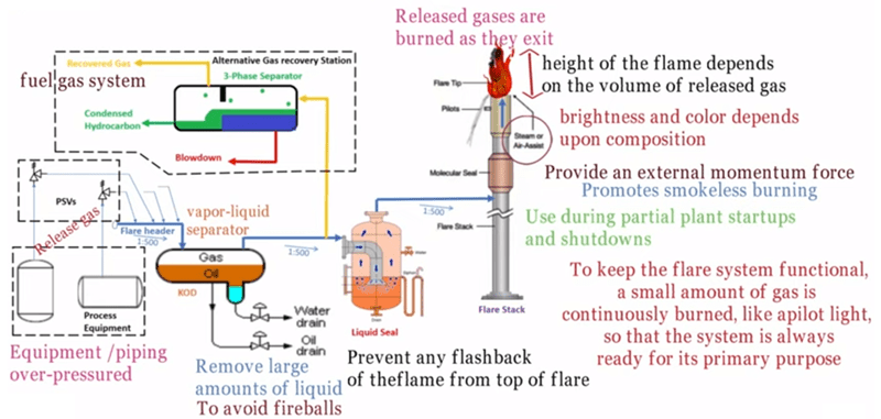
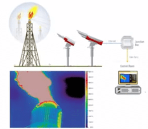
When industrial plant equipment and piping are over-pressurized, the pressure relief valve (PRV) is an essential safety device that automatically releases the over pressured gases or liquids. The released gases or liquids are routed through large, sloped piping systems called flare headers to a vertical elevated flare. Most industrial plant flares have a vapor-liquid separator, also known as a knockout drum, upstream of the flare to remove any large amounts of liquid that may accompany the relieved gases. This is done to avoid “fireballs.” A water seal drum to prevent any flash back of the flame from top of the flare stack is provided. An alternate gas recovery system is used during partial plant startups and shutdowns as well as other times as required. The recovered gas is routed into the fuel gas system of the overall plant. The released gases are burned as the gases exit the flare stack. The “flame height” depends on the volume of the released gases while brightness and color depend on the composition of the gases being burned. Steam is often injected into the flame to provide an external momentum force used for the efficient mixing of air with the relieved gases to promote smokeless burning. To keep the flare functional, a small amount of gas called a “pilot” is continuously burned, so that the system is always ready for its primary purpose of an overpressure safety system. Fig.1 shows an overview of a flare system in a hydrocarbon process facility.
Application of Flare System
- Normal operation of plant – To release any overpressure scenario during the normal operation of any process plant.
- Start-up – Due to the process upset during the start-up of the process plant.
- Maintenance – During planned maintenance and shutdown of the process plant.
- Safety/planned flaring – The planned combustion of gases during a shorter period.
- Emergency situations.
Major Components of a Flare System
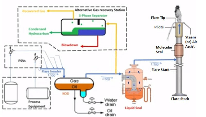
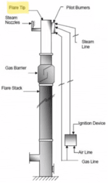
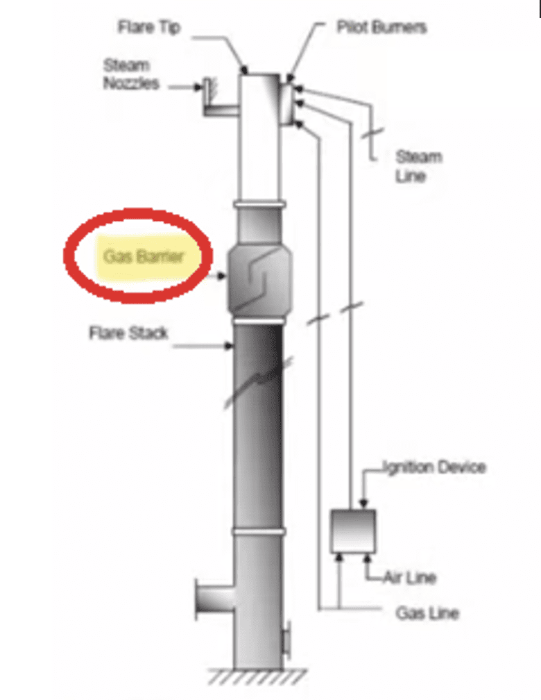
The flare system consists of a network of pipes, specialized valves and equipment. A flare knockout drum (KOD) is used in storing and removing the condensable and entrained liquids, the proprietary seal/water seal to prevent flashback, a single/multiple burner unit, and a flare stack, along with gas pilot and igniter to ignite the mixture of waste gas and air with a provision of external momentum force by steam injection for smokeless flaring.
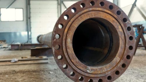
Piping and Valves

The piping should be designed to have minimum pressure drop, avoid potential dead legs and liquid traps. Use of valves in the flare piping system should be kept to minimum and the valves should be “car sealed” to open position. The piping should be open to purging so that explosive mixtures are not built up inside the flare piping system either during startup or during normal operations. Flare lines shall be sloped toward the knockout drum and from the knockout drum toward the flare stack. The minimum slope of flare piping as per API 521 should be 1:450. The general process industry practice is to have the flare line connected to the flare header at a 45 degree via latrolet.
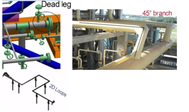 Only 2D loops are allowed on a flare header because where there is the possibility of two-phase flow, 2-D expansion loops are preferred.
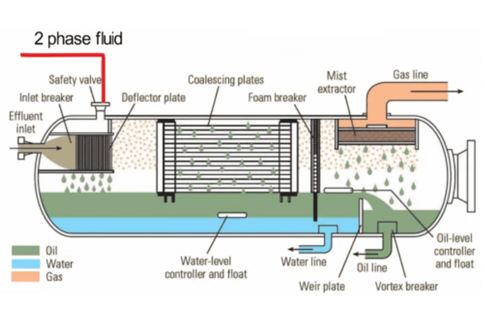
Flare Knock Out Drum (KOD)
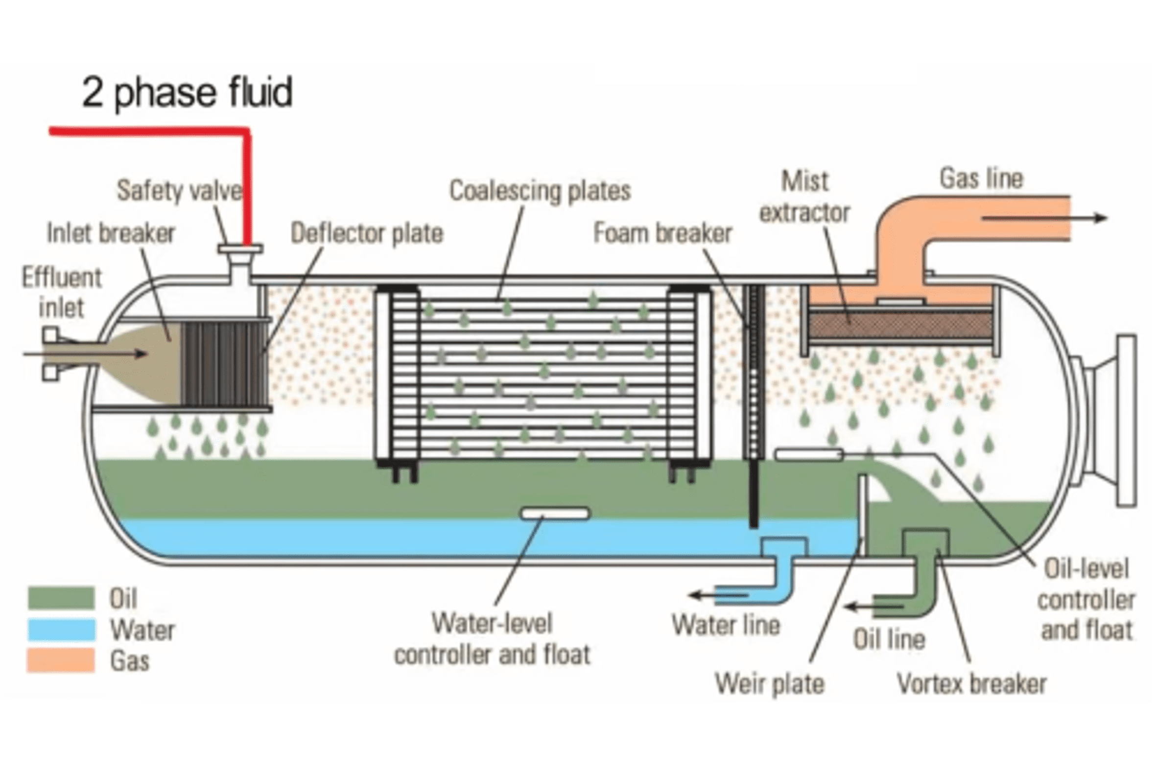 The flare header has a two-phase liquid, and the liquid should be prevented from entering the flare burners. The gas and liquid separate after hitting the deflector plate, the fluids settle at the bottom, and gas comes up due to gravity. This prevents liquids from being discharged into the atmosphere. It prevents and reduces smoke due to the reduced liquid in the flame, increases flare tip life, it allows draining of liquid prior to flare. KOD may be either horizontal or vertical. Horizontal KOD is preferred as the required elevation of the relief header will be lower than what would be required in the vertical drum and thus this would result in a lesser cost option. The KOD drum elevation decides the pipe rack elevation based on 1:500 slope of the main flare header. KOD elevation is determined by the NPSH requirement of the pumps.
Blowdown Drum
The function of a blowdown drum is the same as the knockout drum (KOD). When the fluid quantity is relatively low, a KOD will be sufficient and a blowdown drum may not be required. The blowdown drum tends to be located near the sources close to the battery limits of a process unit or area to reduce the amount of piping subjected to two-phase slug flow. It is not a good practice to design for a significant amount of liquids to run long distances through the plant in the vapor flare header.
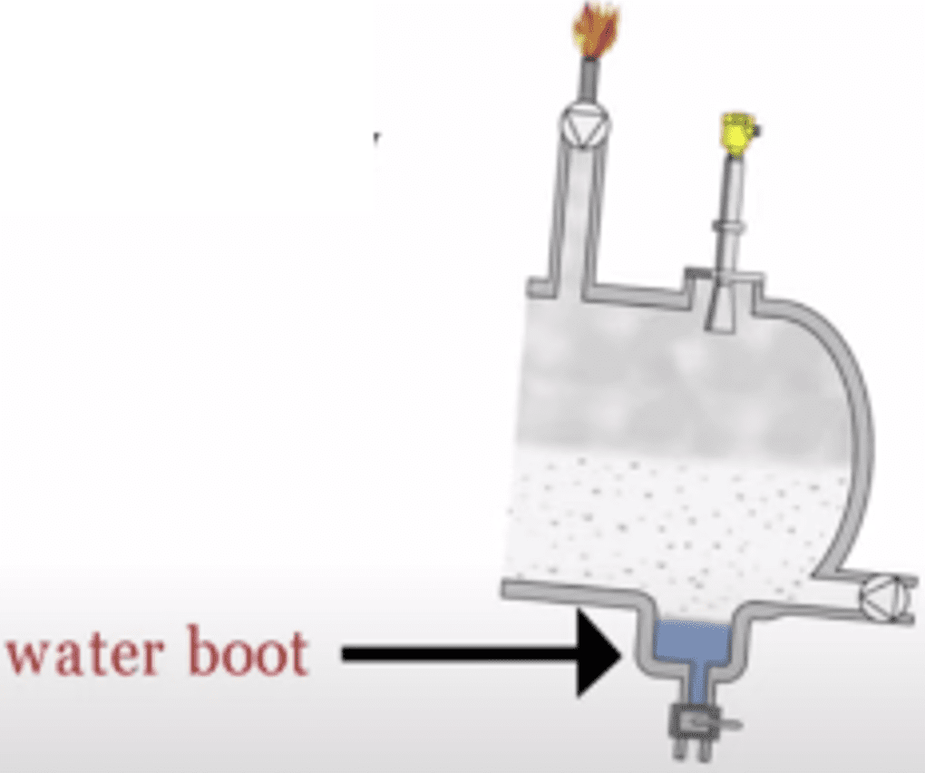
Liquid Seal
A flare system is subjected to explosion hazard when air is present in the system.
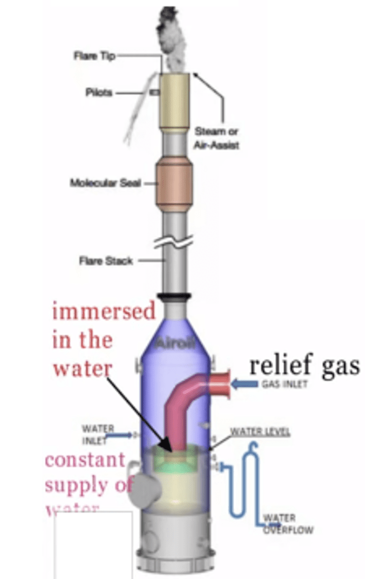
The liquid seal drum is often a vertical vessel installed at the base of the stack. The water level in the drum is maintained by a constant supply of water. The relief gas inlet pipe is projected into the drum and emerges into the water to form a positive seal. The water from the drum is discharged into the oily water sewer system. The drum may require provisions for skimming hydrocarbon liquids from the surface of the water. Removal can be on either a continuous or intermittent basis. Water as a sealing fluid is not recommended for extremely cold releases, but a water glycol mixture of sufficient concentration is used instead.
Flare Stack
Flare stacks are primarily used for burning of flammable gases released by safety valves.
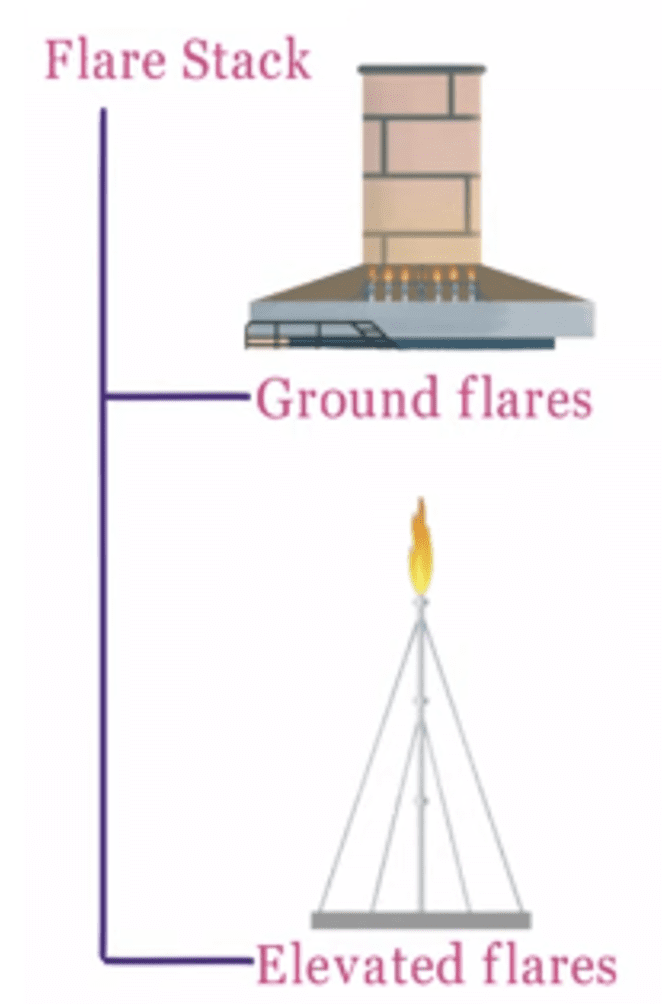 In the industry, the most commonly used type of flare systems are elevated flares and ground flares. Selection of the type of flare is influenced by several factors such as space availability, the characteristic of flare gas; i.e., composition, quantity, pressure, economics, investment and operating costs, public relations and regulations.
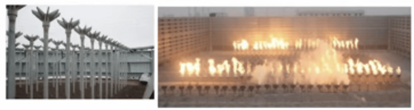
Ground Flare – A ground flare is where flaring of the gases takes place at the ground level. Compared to the elevated flare, ground flare can achieve a smokeless operation with essentially no noise or luminosity problems provided that the design gas to the flare is not exceeded. However, it has poor dispersion of the combustion product because its stack is near to ground. This may result in severe air pollution or hazard if the combustion products are toxic or in the event of flameout. Capital, operating and maintenance costs are high. Ground flares are of two types: 1) Open ground flare and 2) Enclosed ground flare.
Elevated Flare – This flare is the most used flare in the refineries and chemical plants. These have larger capacities than ground flares. The elevated flare can be steam assisted, air assisted or non-assisted. Elevated flares can utilize steam injection or air injection to make smokeless burning with low luminosity up to about 20 percent of maximum flaring load. The disadvantage of steam injection or air injection is that it introduces a source of noise and can cause noise pollution. Capital costs are relatively high and an appreciable plant area may be rendered unavailable for plant equipment because of radiant heat considerations usually up to 300 feet (90 meters) of the flare radius.
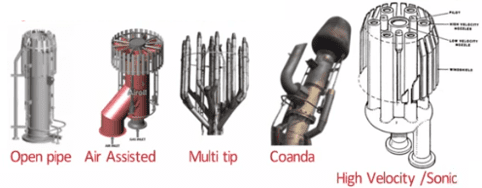
Flare Tip
Flare tip is a large burner or arrangement of small burners fitted at the end of flare risers.
Different types of flare tips are: 1) Open pipe flare tip, 2) Air assisted flare tip, 3) Multi tip, 4) Coanda tip, 5) High velocity/sonic tip.
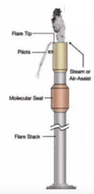
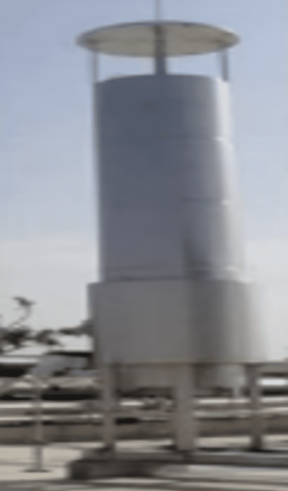
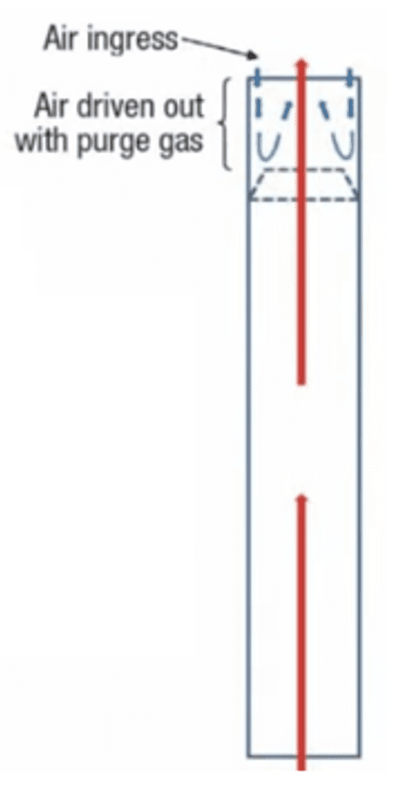
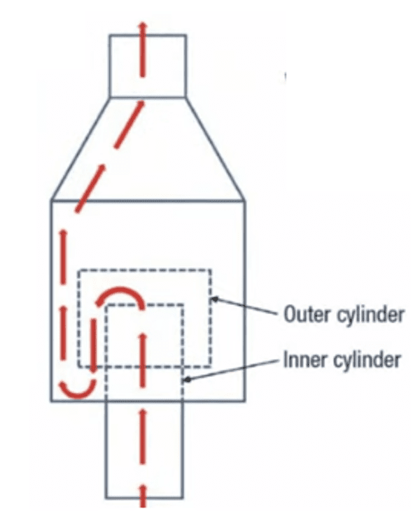
 Gas Barrier: Molecular Seal (or purge reduction seal or velocity seal)
In most flare systems, a molecular seal or a buoyancy seal or a velocity seal is used at the base of the flare tip to ensure a minimum continuous flow of purge gas.
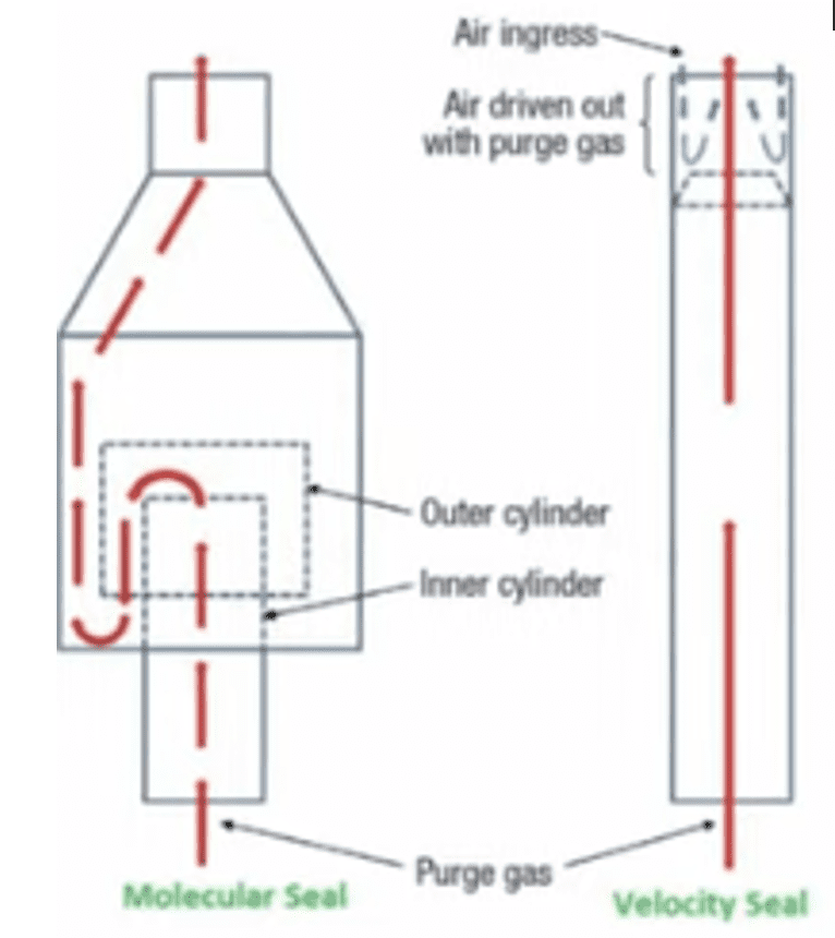
 This helps avoid air ingress to the flare preventing the opportunity for a potentially explosive mixture to develop in the system. Molecular seal systems rely on the differences in densities between the purge gas and ambient air to prevent the air from entering the flare system. The most common type of seal is an inverted can device that causes the gas to flow in an upward direction to be directed through a 180 degree turn at the exit flow. When this happens, gases lighter than air will tend to collect in the upper bends of the apparatus, sealing off the stack against any backflow of air; meanwhile, the heavier gases will tend to settle in the lower part of the bend with the same effect.
|
|
|
Pilot System: To ignite the waste gas
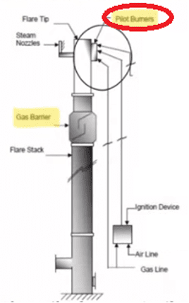
It consists of pilots, pilot igniters and pilot monitors. The Environmental Protection Agency (EPA) requires a continuous flame to be present. This is provided with the help of continuous pilot burners for a reliable ignition as well as stability. The pilot burners must be ignited, and an igniter is used for that. The function of the igniter is to ignite the pilot which in turn lights the flare burners.
There are different types of igniters such as electronic igniter, pressure igniter – i.e., flame front ignition or combination of both.
Pilot Gas Inspirator
 Pilot gas inspirators are required for mixing fuel gas with atmospheric air in a precise ratio to regulate burn characteristics. Here only the pressure of the fuel gas is used to draw and mix the air. An inspirator is a device similar to a venturi tube and an orifice plate.
Pilot Monitoring
An alarm system warns that a pilot at the burner is out. This consists of a chromel-alumel thermocouple installed at the base of each pilot connected to a temperature alarm switch.
Loss of flame temperature then actuates an alarm. This pilot monitoring should be installed mandatorily for each flare.
Types of Flare – Based on Mixing at Flare Tip
An adequate air supply and good mixing are required to complete the combustion and minimize smoke. The various flare designs primarily vary in their accomplishment of mixing. Based on the method of enhancing mixing at the flare tip, the flare can be categorized into four types – 1) Steam Assisted, 2) Air Assisted, 3) Pressure Assisted, and 4) Non-Assisted.
Steam Assisted Flare – These are single burner tips elevated above ground level for safety reasons that burn the vented gas in essentially a diffusion flame. Steam assisted flares are designed to dispose of heavier waste gases which have a greater tendency to smoke. Additional air is induced into the waste gas providing the oxygen necessary for augmented smokeless capacity. Steam assisted flares are typically used in applications where the customer has high pressure steam available on site.
Air Assisted Flares – Some flares use forced air to provide the combustion air and the mixing required for smokeless operation. Air assisted flares dispose of heavier waste gases which have a greater tendency to smoke. Air assisted flares can be employed at sites where steam may not be available. Additional air may be induced into the waste gas providing the oxygen necessary for augmented smokeless capacity. Constant air flow creates a cooling effect for extended flare tip service life. The amount of combustion air can be varied by varying the fan speed.
Pressure Assisted Flares – This flare uses the vent stream pressure to promote mixing at burner tip. If sufficient vent stream pressure is available, these flares can be applied to streams previously requiring steam or air assist for smokeless operations. Pressure assisted flares generally (but not necessarily) have the burner arrangement at ground level and consequently must be located in a remote area of a plant where there is plenty of space available.
Non-Assisted Flares – This is just a flare tip without any auxiliary provision for enhancing the mixing of air into its flame. Its use is limited essentially to gas streams that have a low heat content and low carbon or hydrogen ratio that burns readily without producing smoke. These streams require less air for complete combustion, have lower combustion temperatures that minimize cracking reactions and are most resistant to cracking.
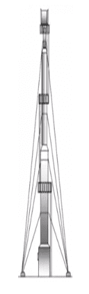
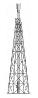
Type of Flare Supports
Elevated flares for onshore facilities can be supported in three ways – 1) Self-Supported Flares, 2) Derrick Supported Flares, 3) Guyed Stacked Flare.
Self-supported Flares:
- The self-supported stack is a free standing stack anchored to the base.

- Used for lower heights where
- radiation exerted is low.
- Uses less space for installation.
- It is more expensive than other designs because it needs greater material to ensure structural integrity over the anticipated condition.
- Stack height for self-supported design ranges from 197 feet to 246 feet (60 to 75 meters).
Derrick Supported Flares:
- Used for 393 feet (120 m) height requirement.
- Used when the stack is large and available land area is limited, i.e., where guy wire support is not suitable.
- This stack is in the center of a derrick in the center of a direct structure and is held to the structure by tie-rods and guides.
- This flare can be built to a considerable height since the system load is spread over the derrick structure.
- Derrick supported flare system is optimum installation for higher heights where higher radiation is exerted.
- This design provides for differential expansion between the stack piping and derrick.
Guyed Stacked Flare:
- Constructed up to height of 591 feet (180 m).
- Stack is anchored by guy wires.
- This flare is the simplest; however, a considerable land mass is required since the guy wires are widely spread apart.
- This flare is used when toxic gases are burned at medium height.
- The space required to erect the guyed support flare is a circle on the ground with the radius equal to the height of the flare stack.
For flare stacks greater than 591 feet, a concrete support structure is required. The support structure systems for elevated flares in offshore facilities are the boom supported and derrick supported. The flare may be either vertical or inclined. The boom is an inclined support structure consisting of tie-rods and guides.
Conclusion
Facilities like petroleum refineries, chemical plants, natural gas processing plants, oil and gas production sites with oil wells, offshore oil and gas rigs/platforms, petrochemical plants, landfills and anything accommodating pressurized hydrocarbons, etc., generate significant amounts of waste products such as methane, volatile organic compounds, organic compounds that have high vapor pressure at room temperature, sulfur related compounds, etc. These waste compounds are toxic, corrosive, flammable and, hence, cannot be directly discharged into the atmosphere due to restrictions imposed by local ordinances or plant practices, because of a lesser permissible explosion or toxic threshold limit at a particular surrounding for local vents in plants. In processes where long and severe waste exhaust temperature is anticipated, the gases cannot be vented locally because of hazardous conditions. In all such cases, the flare is the last line of defense for safe emergency release as burning is the better option.
References
[1] API STD 537 – Flare Details for Petroleum, Petrochemicals and Natural Gas Industries.
[2] API STD 521 : Pressure-relieving and Depressuring Systems.

Nirmal Surendran Menon, PMP®, is the author of the book, Valves Made Easy, along with a coauthor, who is an industry expert as well as a project management professional with 17-plus years of experience in the oil and gas/energy facility construction. He currently works as a senior construction manager overseeing the Pipe Pressure Testing and Pipe Cleaning portfolio with an EPC company with a distinguished reputation in the industry. Menon’s interests include pipe integrity, pipe cleanliness, loss prevention, and human factors for process facilities. He has authored 11 articles and two books, and has sustained national and international acclaim in the industry, having been part of major LNG project construction execution in different geographical locations.
- Nirmal Surendran Menonhttps://oilmanmagazine.com/author/nirmal-surendran-menon/
- Nirmal Surendran Menonhttps://oilmanmagazine.com/author/nirmal-surendran-menon/
- Nirmal Surendran Menonhttps://oilmanmagazine.com/author/nirmal-surendran-menon/
- Nirmal Surendran Menonhttps://oilmanmagazine.com/author/nirmal-surendran-menon/

- Nirmal Surendran Menonhttps://oilmanmagazine.com/author/nirmal-surendran-menon/
- Nirmal Surendran Menonhttps://oilmanmagazine.com/author/nirmal-surendran-menon/
- Nirmal Surendran Menonhttps://oilmanmagazine.com/author/nirmal-surendran-menon/

Ashish Goyal, coauthor of the book Valves Made Easy, is a quality manager at Sempra Infrastructure, a leading energy infrastructure company in North America. With a bachelor’s degree in engineering and over 20 years of experience in the energy industry, he has been involved in all phases of EPCI project delivery.
Collaborating with another industry expert, Menon and Goyal have cowritten this book to share insights and best practices related to valves used in process industries. Their rich and diverse experience aims to inspire and educate readers interested in pursuing a career or enhancing their skills in this field. This book serves as a comprehensive reference for engineers and technicians working with valves across various process industries.
- Ashish Goyalhttps://oilmanmagazine.com/author/ashish-goyal/
- Ashish Goyalhttps://oilmanmagazine.com/author/ashish-goyal/

Oil and gas operations are commonly found in remote locations far from company headquarters. Now, it's possible to monitor pump operations, collate and analyze seismic data, and track employees around the world from almost anywhere. Whether employees are in the office or in the field, the internet and related applications enable a greater multidirectional flow of information – and control – than ever before.