


This article focuses on identifying the minimum requirements for integrating ergonomic principles into the selection of various devices or equipment by identifying the minimum requirements for the facility design with respect to factors such as ease of access and movement and enhancing the operability and maintainability of the equipment in a hydrocarbon facility, as well as the minimum requirements for the working environment to ensure the comfort and enhance the effectiveness of operating and maintenance personnel working in the hydrocarbon facility. Finally, this article sheds light on identifying the minimum requirements for evacuation and escape from facilities.
Equipment Identification
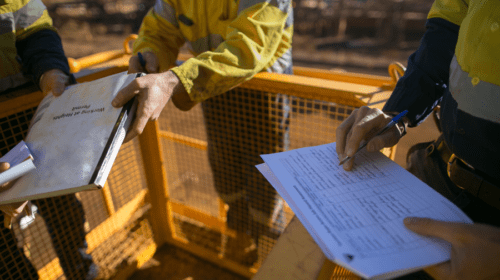
Permanent, unique identification tags for every piece of equipment or valve, ensuring primary identification that can be read from normal walkways, is mandatory in any operating facility. In order to access the equipment, proper identification of the equipment is very important. All major equipment in a facility should be labelled. Typical list of equipment in a facility are as below:
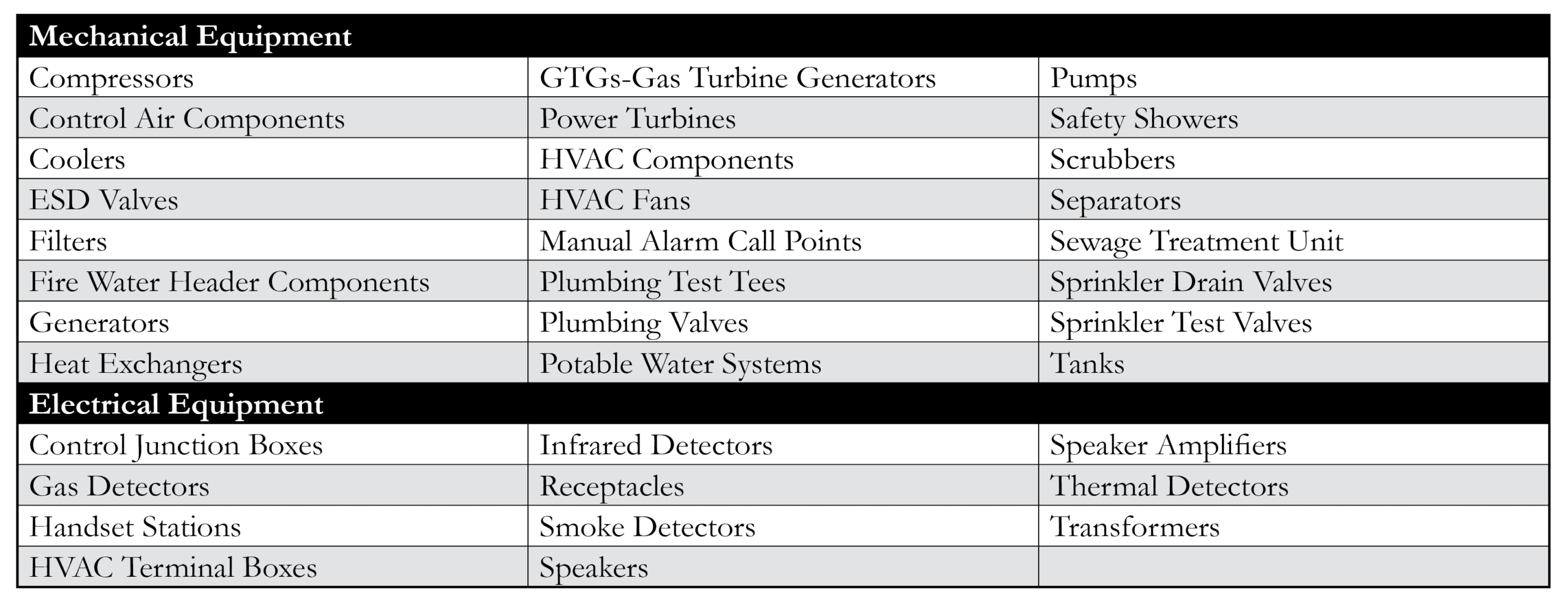 All labels should have a functional description in a human-readable format. All regulatory signs and labels should use both human-readable text and symbols to convey the information.
Access to Equipment and Moving Around
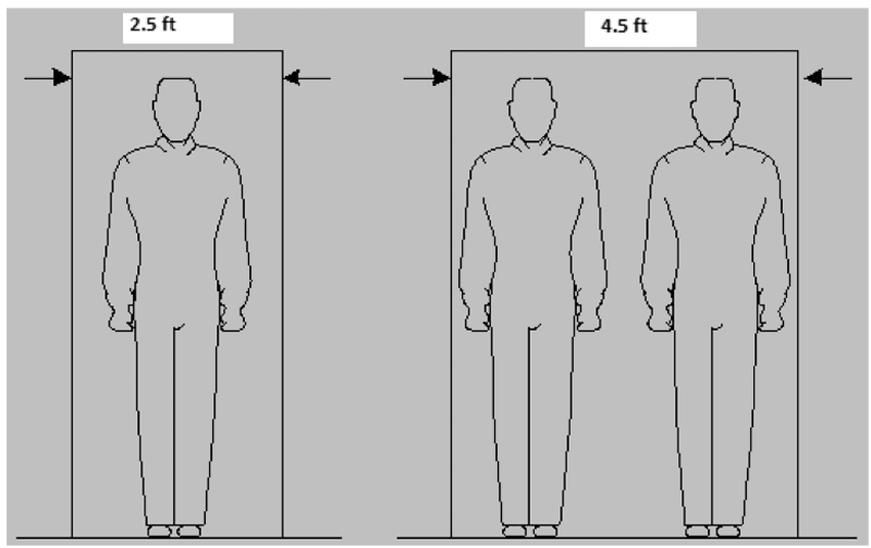
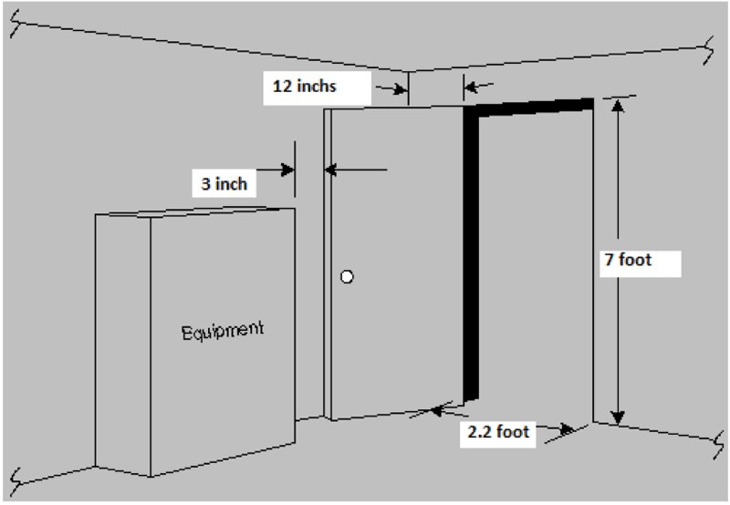
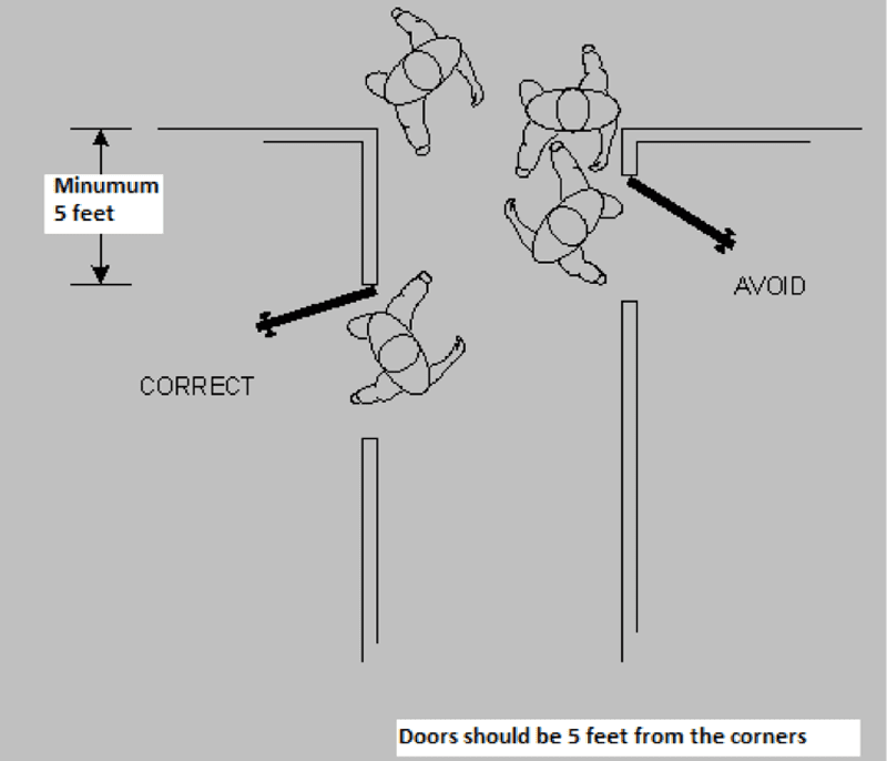
Ease of access to equipment and movement is to be ensured by designing the corridors, access ways, doors, exits, etc., in an ergonomic friendly way. A one-way corridor or access way should have a minimum of two and a half feet (760 mm), and a two-way corridor or access way should have a minimum of 4.5 ft (1370 mm). Refer to Figure A-1. A minimum of two exits are to be provided in enclosed, staffed areas where fuel, chemicals or other flammable materials are used. These should be doors hinged to swing to the outside or kick-out panels. In areas housing large pieces of equipment, such as compressors, the exits should be located so that it is possible to exit from either side of the equipment. Minimum door dimension requirement may be followed as per Figure A-2. It must be ensured that the doors are at least five feet (1500 mm) from corners, i.e., junctures between two corridors, or where a single corridor turns a corner as per Figure A-2b.
Equipment Access for Operability
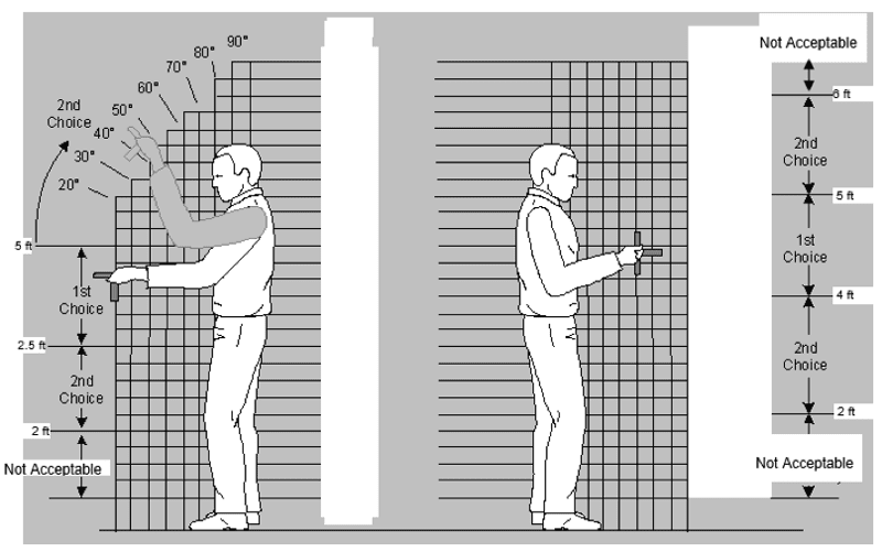
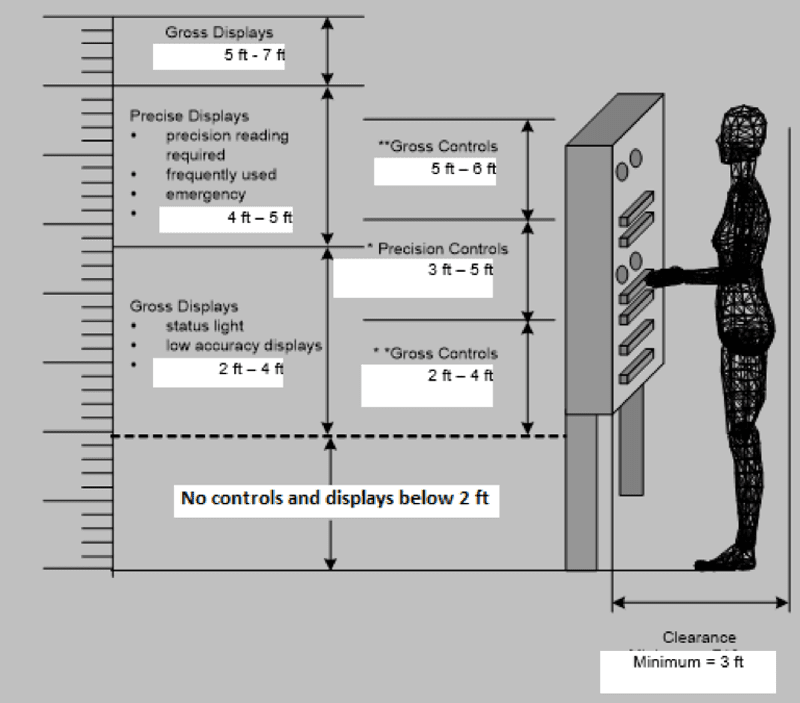
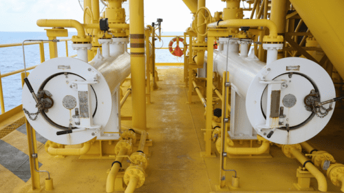
Hydrocarbon facilities have numerous types of equipment such as compressors, pumps, and instruments such as local panels, piping system and valves, etc. Mechanical equipment, such as pumps, compressors, etc., are to be positioned on a raised platform with access from all sides to avoid having to maintain the equipment while crouching at floor level. Factors to consider in determining if placing a pump on a raised platform is practical include the need to provide a rigid support structure for the equipment and the desire to keep equipment piping and valve at a reasonable height for operations and maintenance. For mobility around piping systems and valves, ensure that gangways to the location of large valves in large diameter pipework are sufficiently wide to move the valves to and from the location – one foot is normally required on either side of the equipment or trolley. Recommended mounting heights for valve hand wheels is shown below in Figure A-3. For mobility and workspace around the local instrument locations, clearance is to be ensured above and below control valves and that this is sufficient to include access by mobile equipment in order to facilitate maintenance tasks. Instruments are to be located so that they are visible from the normal work position without needing to stand on other items of equipment, components, pipework, cable trays, handrails, etc. Locate important displays, those requiring precise, frequent or emergency use, in a primary viewing area and at a height of between four to five feet above the standing surface as indicated on Figure A-4.
Equipment Access for Maintainability
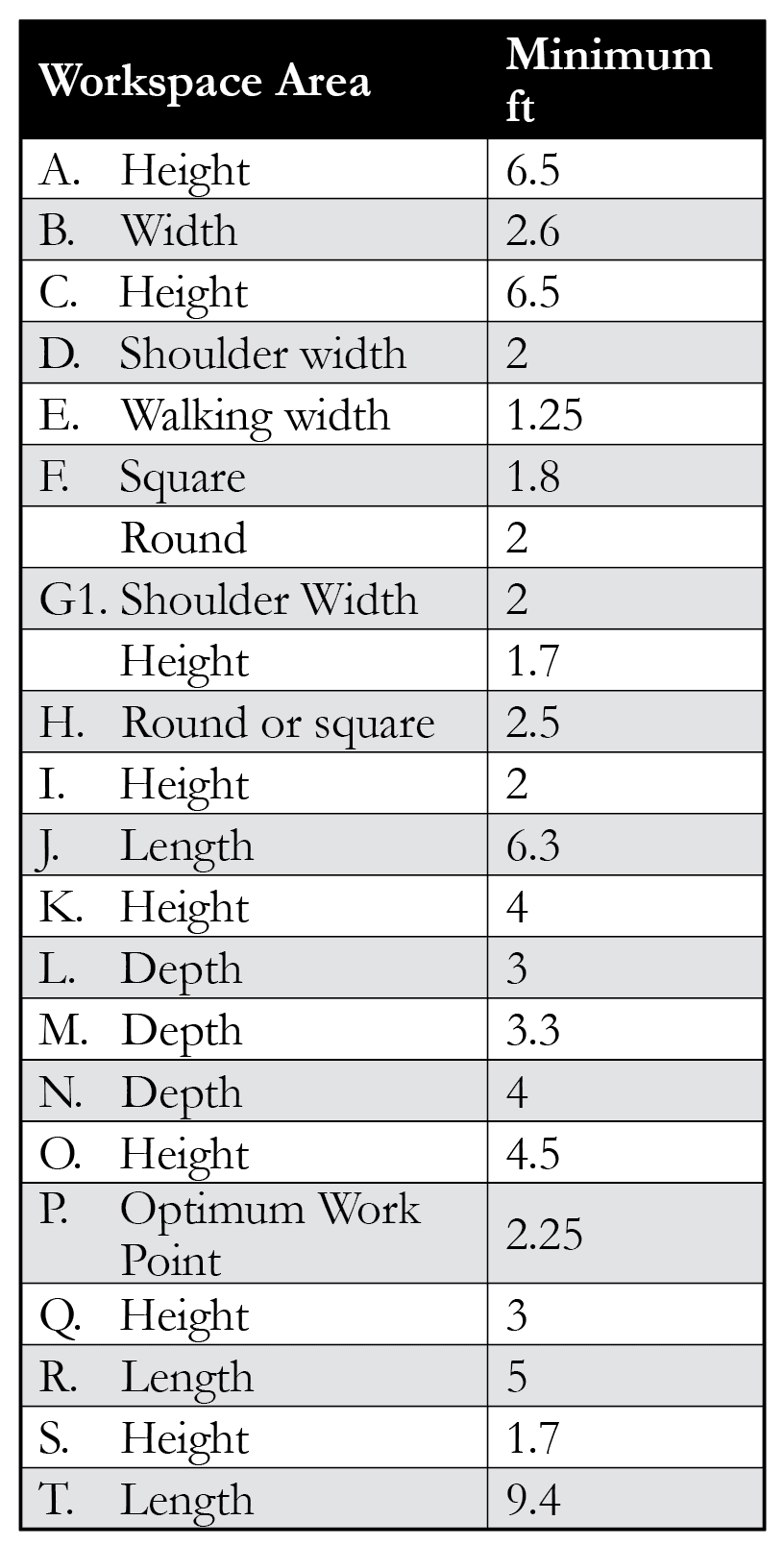
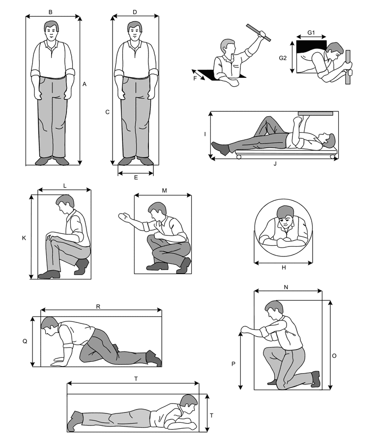
The equipment should be provided access by overhead crane, local permanent hoist or lifting beam plus a portable crane, forklift truck or trolley. The design of equipment should be such that it can be subdivided into smaller sub-units to facilitate removal, repair or replacement of the sub-units. “Lifting eyes” are provided for equipment weighing more than 150 lbs. with a minimum of four inches of space around the eye. The lifting eyes are to be correctly located with regard to the center of gravity of the item. Lifting limits on hoists, booms and beams should be labelled and identified clearly along with lifting zones and laydown areas by use of floor markings. Adequate workspace should be available for the use and placement of tools, and for placing spare parts and components of equipment in the work area during their repair/replacement by taking into consideration the number of personnel required to do the work, equipment requirements (including maintenance instructions, check sheets, logbooks and other documentation that may be referred to), and body positions they may need to adopt. The type, size and shape of access apertures chosen usually includes the consideration of the type of clothing and PPE that would be worn by the personnel. The workspace dimensions based on American Society for Testing Materials (ASTM) 1988 is shown on Figure A-5 and Table B-1.
Working Environment
A good working environment in a facility is ensured by adequate lighting, a good thermal environment, proper ventilation, adequate noise levels and excellent weather protection. Weather protection should also take into account the protection factor that is required from adverse weather on personnel related to wind, rain, high temperature and humidity. Muster points should also have areas that give shelter from the elements related to adverse conditions mentioned above (wind, rain, high temperature and humidity).
Evacuation and Escape
An operating hydrocarbon facility normally has a primary evacuation route and a secondary evacuation route. The evacuation routes are provided as direct as possible avoiding frequent change in direction. In the event of changes in elevation (due to different deck levels), the evacuation is carried out via stairs or ramps. Ladders are only used in rare events when stairs or ramps are not available. The primary evacuation route passage width should be at least five feet (1525 millimeters) and should be maintained for the stairways, which are part of the evacuation route. Dead leg areas over 16 feet long are provided with at least two exits leading to evacuation routes. The emergency door and hatches during the emergency personnel movement are designed in such a way that the door opens in the direction of the moving personnel. These are designed in such a way that they are easily accessible, easy to operate even in dark and quick to open (by a maximum force of 30 lbs.). Emergency doors and hatches are clearly marked on both sides of the door and hatch to prevent obstruction of the exit. Dimensions of escape hatches are large enough to accommodate personnel wearing heavy clothing, breathing apparatus, life jackets, etc. Minimum dimensions of hatches for sideways access through rectangular aperture in a vertical surface: Light clothing: Two and a half feet high by two and a half feet wide (2.5’ x 2.5’), bulky clothing: two and a half feet high by three feet wide (2.5’ x 3’). For top and bottom access through a rectangular aperture in a horizontal surface the dimensions are: Light clothing: Two feet by two and a half feet (2’ x 2.5’), bulky clothing: two and a half feet by three feet (2.5’ x 3’). For circular apertures, they are: Minimum diameter equals two and a half feet (2.5’).
Human factors ergonomics mainly focus on attributes such as moving to and around the workspace, access, visibility and working positions, manual handling (laydown areas, lifting arrangement requirements, etc.), labelling, status identification (such as system alarms and beacons), communication and environmental conditions, among others, to be implemented during the design and engineering of a facility, in order to ensure smooth operations and maintenance of the facility post startup during its operations lifetime.

Nirmal Surendran Menon, PMP®, is the author of the book, Valves Made Easy, along with a coauthor, who is an industry expert as well as a project management professional with 17-plus years of experience in the oil and gas/energy facility construction. He currently works as a senior construction manager overseeing the Pipe Pressure Testing and Pipe Cleaning portfolio with an EPC company with a distinguished reputation in the industry. Menon’s interests include pipe integrity, pipe cleanliness, loss prevention, and human factors for process facilities. He has authored 11 articles and two books, and has sustained national and international acclaim in the industry, having been part of major LNG project construction execution in different geographical locations.
-
Nirmal Surendran Menonhttps://oilmanmagazine.com/author/nirmal-surendran-menon/
-
Nirmal Surendran Menonhttps://oilmanmagazine.com/author/nirmal-surendran-menon/
-
Nirmal Surendran Menonhttps://oilmanmagazine.com/author/nirmal-surendran-menon/
-
Nirmal Surendran Menonhttps://oilmanmagazine.com/author/nirmal-surendran-menon/
-
Nirmal Surendran Menonhttps://oilmanmagazine.com/author/nirmal-surendran-menon/
-
Nirmal Surendran Menonhttps://oilmanmagazine.com/author/nirmal-surendran-menon/
-
Nirmal Surendran Menonhttps://oilmanmagazine.com/author/nirmal-surendran-menon/

Oil and gas operations are commonly found in remote locations far from company headquarters. Now, it's possible to monitor pump operations, collate and analyze seismic data, and track employees around the world from almost anywhere. Whether employees are in the office or in the field, the internet and related applications enable a greater multidirectional flow of information – and control – than ever before.